Somos responsables de la construcción-----somos responsables de la fabricación-----somos responsables de la formación

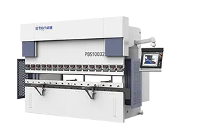
Una plegadora hidráulica es una máquina de conformado esencial utilizada para doblar chapas metálicas en ángulos y perfiles precisos mediante una fuerza hidráulica controlada. Se utiliza ampliamente en la fabricación industrial de chapa metálica, donde se requiere una alta precisión de plegado, una presión de conformado estable y resultados repetibles. Diseñadas para talleres de producción y entornos de fabricación OEM, las plegadoras hidráulicas ofrecen un rendimiento de plegado confiable para una amplia gama de materiales metálicos y espesores. El sistema hidráulico garantiza una distribución uniforme de la fuerza durante las operaciones de plegado, ayudando a los fabricantes a mantener una calidad de conformado constante a lo largo de ciclos de producción continuos.
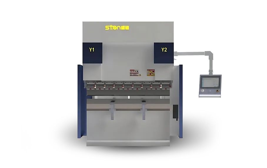
| No. | Nombre | 63/1500 | 63/2100 | 63/2550 | 100/3200 | 100/4100 | 150/3200 | 150/4100 | 220/3200 | 220/4100 | 250/3200 | 250/4100 | 320/3200 | 320/4100 | Unidad | |
| 1 | Presión nominal | 630 | 630 | 630 | 1000 | 1000 | 1500 | 1500 | 2200 | 2200 | 2500 | 2500 | 3200 | 3200 | KN | |
| 2 | Longitud de plegado | 1500 | 2100 | 2550 | 3200 | 4100 | 3200 | 4100 | 3200 | 4100 | 3200 | 4100 | 3200 | 4100 | MM | |
| 3 | Espaciado entre columnas | 1200 | 1600 | 2050 | 2700 | 3600 | 2700 | 3600 | 2700 | 3600 | 2700 | 3600 | 2700 | 3600 | MM | |
| 4 | Carrera del cilindro | 215 | 215 | 215 | 215 | 215 | 215 | 215 | 215 | 215 | 225 | 225 | 315 | 315 | MM | |
| 5 | Altura de apertura | 580 | 580 | 580 | 580 | 580 | 580 | 580 | 580 | 580 | 580 | 580 | 680 | 680 | MM | |
| 6 | Profundidad de la garganta | 350 | 350 | 350 | 390 | 390 | 405 | 405 | 405 | 405 | 405 | 405 | 405 | 405 | MM | |
| 7 | Velocidad de desplazamiento del control deslizante | Rápido, ¡bájate! | 185 | 185 | 185 | 220 | 220 | 180 | 180 | 160 | 160 | 150 | 150 | 130 | 130 | MM/S |
| 8 | Avance de los trabajos | 19 | 19 | 19 | 17 | 17 | 14 | 14 | 12 | 12 | 10 | 10 | 9.5 | 9.5 | MM/S | |
| 9 | Volver | 180 | 180 | 180 | 210 | 180 | 180 | 170 | 160 | 150 | 150 | 140 | 120 | 110 | MM/S | |
| 10 | Recorrido del eje X | 500 | 500 | 500 | 500 | 500 | 500 | 500 | 500 | 500 | 500 | 500 | 500 | 500 | 500 | |
| 11 | Recorrido del eje R | 200 | 200 | 200 | 200 | 200 | 200 | 200 | 200 | 200 | 200 | 200 | 200 | 200 | 200 | |
| 12 | Velocidad del eje X | 400 | 400 | 400 | 400 | 400 | 400 | 400 | 400 | 400 | 400 | 400 | 400 | 400 | 400 | |
| 13 | Velocidad del eje R | 200 | 200 | 200 | 200 | 200 | 200 | 200 | 200 | 200 | 200 | 200 | 200 | 200 | 200 | |
| 14 | Potencia del motor principal | 8.7 | 8.7 | 8.7 | 10.8 | 10.8 | 13.2 | 13.2 | 16.7 | 16.7 | 16.7 | 16.7 | 22 | 22 | KW | |
| 15 | Volumen de aceite hidráulico | 130 | 180 | 200 | 300 | 400 | 300 | 400 | 300 | 400 | 300 | 400 | 400 | 500 | L | |
| 16 | Dimensiones (L × An × Al) | 2000/1620/2470 | 2600/1620/2470 | 3150/1620/2470 | 3720/1720/2550 | 4620/1720/2550 | 3780/1730/2600 | 4680/1730/2600 | 3830/1800/2670 | 4730/1800/2670 | 3830/1800/2670 | 4730/1800/2670 | 3880/2100/3250 | 4760/2100/3250 | MM | |
| 17 | Espesor de la máquina herramienta (placa vertical, carro, mesa de trabajo) | 40/50/60 | 40/50/60 | 40/50/60 | 50/60/80 | 50/70/90 | 60/70/90 | 60/80/100 | 70/80/100 | 70/90/110 | 70/80/100 | 70/90/110 | 80/90/110 | 80/100/120 | MM | |
| 18 | Diámetro interior del cilindro | 115 | 115 | 115 | 150 | 150 | 180 | 180 | 220 | 220 | 230 | 230 | 270 | 270 | MM | |
| 19 | Diámetro del vástago del cilindro | 110 | 110 | 110 | 145 | 145 | 173 | 173 | 210 | 210 | 220 | 220 | 260 | 260 | MM | |
| 20 | Peso de la máquina | 4500 | 5000 | 6000 | 8500 | 10500 | 9200 | 11600 | 11000 | 13200 | 11000 | 13200 | 16800 | 19000 | kg | |
| 21 | Caudal de la bomba de aceite | 16 | 16 | 16 | 20 | 20 | 25 | 25 | 32 | 32 | 32 | 32 | 40 | 40 | L | |
Las plegadoras hidráulicas están diseñadas para mantener la precisión de conformado en condiciones de carga elevada. La rigidez estructural y el control hidráulico preciso trabajan juntos para ofrecer resultados de plegado estables durante un funcionamiento prolongado.
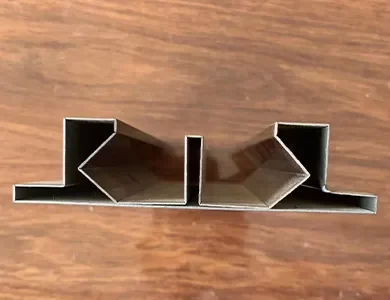
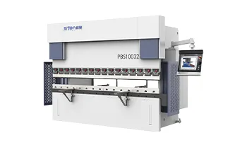
Plegadora Servohidráulica Eléctrica Serie PBS de STON
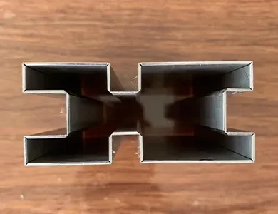
Plegadora Servohidráulica Eléctrica Serie PBS de STON
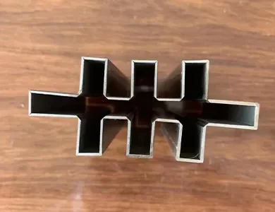
Plegadora Servohidráulica Eléctrica Serie PBS de STON
Características principales
Los sistemas hidráulicos proporcionan una fuerza estable y ajustable, adecuada para el plegado de chapas metálicas gruesas y de alta resistencia.

La presión hidráulica controlada permite un control preciso del ángulo y una precisión de plegado repetible.
Adecuada para acero al carbono, acero inoxidable, aluminio y otros materiales de chapa metálica comunes.
El movimiento hidráulico garantiza un conformado suave sin impactos bruscos, lo que reduce la tensión en el material.
Diseñado para un funcionamiento a largo plazo en entornos de fabricación exigentes.
Admite diferentes longitudes de doblado, configuraciones de herramientas y configuraciones de producto.
Una calidad constante en el plegado es fundamental para garantizar el ajuste y el ensamblaje adecuados de las piezas metálicas fabricadas. Un control hidráulico impreciso o una estructura inestable de la máquina pueden provocar desviaciones angulares, defectos en la superficie y un mayor volumen de reacondicionamiento. Nuestras prensas plegadoras hidráulicas están diseñadas para ofrecer un rendimiento de plegado estable a lo largo de todo el ciclo de producción. La presión de conformado controlada, la precisión constante en el ángulo y el movimiento suave ayudan a los fabricantes a mejorar la eficiencia general de la producción y a garantizar la confiabilidad de los procesos posteriores de ensamblaje y soldadura.
Una prensa plegadora hidráulica funciona gracias a la interacción coordinada de múltiples sistemas mecánicos, hidráulicos y de control. Un rendimiento confiable en el plegado depende no solo de la potencia hidráulica, sino también de la estructura de la máquina, el control de movimiento, la precisión de las herramientas y la coordinación del sistema.
Cada prensa plegadora hidráulica está diseñada como un sistema completo de conformado en el que el circuito hidráulico, la estructura del bastidor, las unidades de accionamiento y la plataforma de control CNC funcionan de manera integrada. Este diseño basado en un sistema garantiza una precisión de conformado estable, una distribución uniforme de la fuerza y una larga vida útil en condiciones de uso industrial continuo.
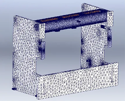
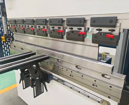
Proporciona rigidez para soportar una gran fuerza de flexión y mantener la estabilidad estructural.
Genera una presión controlada para facilitar operaciones de doblado precisas y sin problemas.
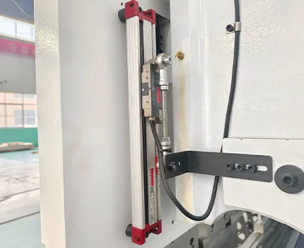
Controla la velocidad de doblado y la precisión de posicionamiento a lo largo de todo el proceso de conformado.
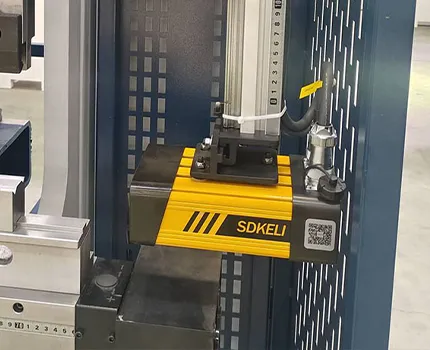
Garantiza la seguridad del operador y un funcionamiento estable de la máquina durante procesos de conformado que requieren gran fuerza.
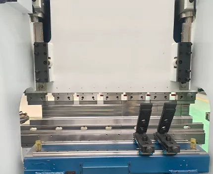
Controla el movimiento del pistón y la precisión de posicionamiento durante los ciclos de doblado.
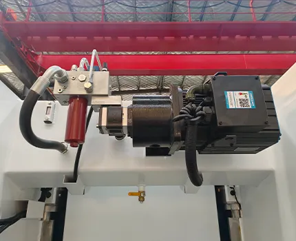
Controla los parámetros de doblado, el ángulo y garantiza una ejecución repetible de la producción.
Creemos en el establecimiento de relaciones sólidas y transparentes con nuestros clientes. Por eso invitamos a nuestros socios a visitar nuestras vanguardistas instalaciones de fabricación y ver de cerca nuestro proceso de producción.
 Anthony
Gerente de Adquisiciones, Climatización
Fábrica de componentes (Alemania)
 Jeffrey
Propietario de una fábrica de utensilios de cocina de acero inoxidable
Fabricante (EE. UU.)
 Jared
Jared– Director de Operaciones, Cuadros Eléctricos
Fábrica (Canadá)
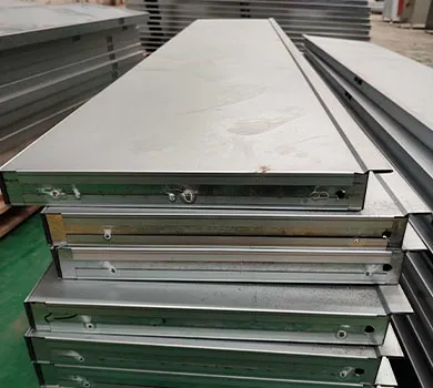
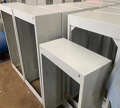
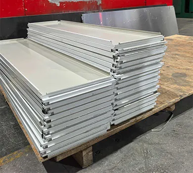
Una prensa plegadora hidráulica se utiliza para doblar láminas de metal en ángulos y formas específicas mediante la aplicación de una fuerza hidráulica controlada. Se utiliza comúnmente en la fabricación industrial para la producción de gabinetes, carcasas, marcos y componentes estructurales.
Las prensas plegadoras hidráulicas utilizan la presión del fluido para generar la fuerza de doblado, lo que permite un movimiento suave y un control estable de la fuerza. Esto las hace adecuadas para doblar materiales más gruesos y mantener una precisión de conformado constante.
Las prensas plegadoras hidráulicas pueden procesar láminas de acero al carbono, acero inoxidable, aluminio y otros metales. Los parámetros de plegado se ajustan en función del espesor del material, su resistencia y los requisitos de plegado.
La precisión se mantiene gracias a un control preciso de la presión hidráulica, una estructura rígida de la máquina, herramientas precisas y un posicionamiento controlado por CNC, lo cual, en conjunto, garantiza resultados de doblado repetibles.
Sí, las prensas plegadoras hidráulicas están diseñadas para un uso industrial a largo plazo. Los sistemas hidráulicos estables, los componentes duraderos y un mantenimiento adecuado permiten un funcionamiento continuo y confiable en entornos de fabricación.
Tanto si está actualizando una línea existente como si está iniciando un nuevo proyecto, STON personalizará una solución CNC para su producción.